
UEFI的启动流程
前言
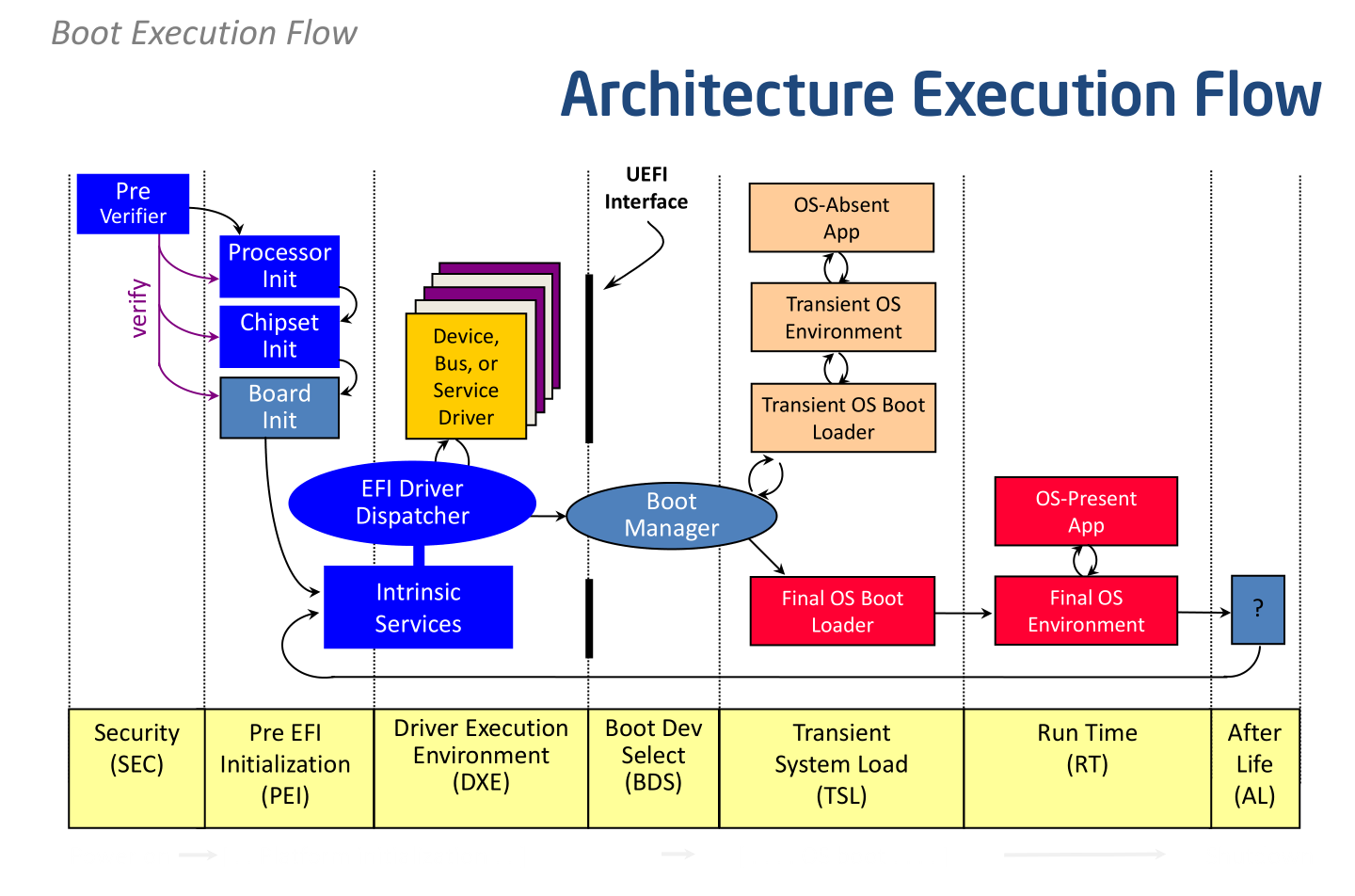
UEFI的启动共有7个阶段,分别是:SEC->PEI->DXE->BDS->TSL->RT->AL,下面以UDK代码的形式记录下整个流程。
SEC 阶段
SEC是UEFI启动流程的第一个阶段,此阶段又可分为前后两部分,前部分为Pre-SEC,后部分为SEC入口。
1.Pre-SEC
在CPU发出RESET信号后,开始执行第一行代码,x86的架构定义的第一行代码地址是0xFFFF FFF0,位于UefiCpuPkg\ResetVector\Vtf0\Ia16\ResetVectorVtf0.asm中,如下:
resetVector:
;
; Reset Vector
;
; This is where the processor will begin execution
;
    nop
    nop
    jmp     EarlyBspInitReal16
X86的机器可以用RW查看0xFFFF FFF0处的内存,如下:

这里所看到的是机器码,90 表示汇编中的nop空操作,E9表示汇编指令中的Jmp,后是跳转的地址。在IA-32架构中,SEC文件只有16个byte的空间在0xFFFF FFF0处作为入口点(Ref1)。
通过跟踪EarlyBspInitReal16可定位到文件UefiCpuPkg\ResetVector\Vtf0\Main.asm中:
;------------------------------------------------------------------------------
; @file
; Main routine of the pre-SEC code up through the jump into SEC
;
; Copyright (c) 2008 - 2009, Intel Corporation. All rights reserved.<BR>
; This program and the accompanying materials
; are licensed and made available under the terms and conditions of the BSD License
; which accompanies this distribution.  The full text of the license may be found at
; http://opensource.org/licenses/bsd-license.php
;
; THE PROGRAM IS DISTRIBUTED UNDER THE BSD LICENSE ON AN "AS IS" BASIS,
; WITHOUT WARRANTIES OR REPRESENTATIONS OF ANY KIND, EITHER EXPRESS OR IMPLIED.
;
;------------------------------------------------------------------------------


BITS    16

;
; Modified:  EBX, ECX, EDX, EBP
;
; @param[in,out]  RAX/EAX  Initial value of the EAX register
;                          (BIST: Built-in Self Test)
; @param[in,out]  DI       'BP': boot-strap processor, or
;                          'AP': application processor
; @param[out]     RBP/EBP  Address of Boot Firmware Volume (BFV)
; @param[out]     DS       Selector allowing flat access to all addresses
; @param[out]     ES       Selector allowing flat access to all addresses
; @param[out]     FS       Selector allowing flat access to all addresses
; @param[out]     GS       Selector allowing flat access to all addresses
; @param[out]     SS       Selector allowing flat access to all addresses
;
; @return         None  This routine jumps to SEC and does not return
;
Main16:
    OneTimeCall EarlyInit16

    ;
    ; Transition the processor from 16-bit real mode to 32-bit flat mode
    ;
    OneTimeCall TransitionFromReal16To32BitFlat

BITS    32

    ;
    ; Search for the Boot Firmware Volume (BFV)
    ;
    OneTimeCall Flat32SearchForBfvBase

    ;
    ; EBP - Start of BFV
    ;

    ;
    ; Search for the SEC entry point
    ;
    OneTimeCall Flat32SearchForSecEntryPoint

    ;
    ; ESI - SEC Core entry point
    ; EBP - Start of BFV
    ;

%ifdef ARCH_IA32

    ;
    ; Restore initial EAX value into the EAX register
    ;
    mov     eax, esp

    ;
    ; Jump to the 32-bit SEC entry point
    ;
    jmp     esi

%else

    ;
    ; Transition the processor from 32-bit flat mode to 64-bit flat mode
    ;
    OneTimeCall Transition32FlatTo64Flat

BITS    64

    ;
    ; Some values were calculated in 32-bit mode.  Make sure the upper
    ; 32-bits of 64-bit registers are zero for these values.
    ;
    mov     rax, 0x00000000ffffffff
    and     rsi, rax
    and     rbp, rax
    and     rsp, rax

    ;
    ; RSI - SEC Core entry point
    ; RBP - Start of BFV
    ;

    ;
    ; Restore initial EAX value into the RAX register
    ;
    mov     rax, rsp

    ;
    ; Jump to the 64-bit SEC entry point
    ;
    jmp     rsi

%endif
该文件主要完成几个任务:
1).从16位Real Mode切换到32 Flat Mode(通过该模式可以访问代码,数据和堆栈的处理器的整个地址范围,是PEI入口的先决条件之一,Ref2)
2).查找Boot Firmware Volume (BFV,存放PEI相关代码部分,Ref3)
3).查找SEC入口点
4).初始化临时内存(Cache As Ram)
5).若是64位系统,则切换到64位Flat Mode
6).调用SEC入口SecStartup
;
; Pass entry point of the PEI core
;
mov     edi, 0FFFFFFE0h
push    DWORD PTR ds:[edi]

;
; Pass BFV into the PEI Core
;
mov     edi, 0FFFFFFFCh
push    DWORD PTR ds:[edi]

;
; Pass stack size into the PEI Core
;
mov     ecx, [ebp - 4]
mov     edx, [ebp - 8]
push    ecx       ; RamBase

sub     edx, ecx
push    edx       ; RamSize

;
; Pass Control into the PEI Core
;
call SecStartup
2.SEC入口
位于UefiCpuPkg\SecCore\SecMain.c中
1.从BFV中找到PEI入口(SecStartup -> SecStartupPhase2 -> FindAndReportEntryPoints)
2.将初始化的临时内存地址及BFV地址等数据传递给PEI入口((*PeiCoreEntryPoint) (SecCoreData, PpiList)),SecCoreData定义如下:
///
/// EFI_SEC_PEI_HAND_OFF structure holds information about
/// PEI core's operating environment, such as the size of location of
/// temporary RAM, the stack location and BFV location.
///
typedef struct _EFI_SEC_PEI_HAND_OFF {
  ///
  /// Size of the data structure.
  ///
  UINT16  DataSize;

  ///
  /// Points to the first byte of the boot firmware volume,
  /// which the PEI Dispatcher should search for
  /// PEI modules.
  ///
  VOID    *BootFirmwareVolumeBase;

  ///
  /// Size of the boot firmware volume, in bytes.
  ///
  UINTN   BootFirmwareVolumeSize;

  ///
  /// Points to the first byte of the temporary RAM.
  ///
  VOID    *TemporaryRamBase;

  ///
  /// Size of the temporary RAM, in bytes.
  ///
  UINTN   TemporaryRamSize;

  ///
  /// Points to the first byte of the temporary RAM
  /// available for use by the PEI Foundation. The area
  /// described by PeiTemporaryRamBase and PeiTemporaryRamSize
  /// must not extend outside beyond the area described by
  /// TemporaryRamBase & TemporaryRamSize. This area should not
  /// overlap with the area reported by StackBase and
  /// StackSize.
  ///
  VOID    *PeiTemporaryRamBase;

  ///
  /// The size of the available temporary RAM available for
  /// use by the PEI Foundation, in bytes.
  ///
  UINTN   PeiTemporaryRamSize;

  ///
  /// Points to the first byte of the stack.
  /// This are may be part of the memory described by
  /// TemporaryRamBase and TemporaryRamSize
  /// or may be an entirely separate area.
  ///
  VOID    *StackBase;

  ///
  /// Size of the stack, in bytes.
  ///
  UINTN   StackSize;
} EFI_SEC_PEI_HAND_OFF;
PEI 阶段

PEI阶段的入口函数是PeiCoreEntry:
/**
  This routine is invoked in switch stack as PeiCore Entry.

  @param SecCoreData     Points to a data structure containing information about the PEI core's operating
                         environment, such as the size and location of temporary RAM, the stack location and
                         the BFV location.
  @param Private         Pointer to old core data that is used to initialize the
                         core's data areas.
**/
VOID
EFIAPI
PeiCoreEntry (
  IN CONST EFI_SEC_PEI_HAND_OFF    *SecCoreData,
  IN PEI_CORE_INSTANCE             *Private
  )
{
  //
  // Entry PEI Phase 2
  //
  PeiCore (SecCoreData, NULL, Private);
}
PeiCoreEntry又调用PeiCore,位于文件:MdeModulePkg\Core\Pei\PeiMain\PeiMain.c中,此函数主要初始化Pei Core Service,然后再调用PeiDispatcher调度PEI Module(PEIM),每个PEIM都是一个独立的模块,负责初始化相应的某一功能,如初始化CPU,内存控制器及其它IO控制器等,并把相关数据存储在HOB中。
PEIM调度完毕,真正的内存便可以使用了,此时PeiCore会重新调用一次,将初始化的数据从临时内存迁移到新的内存中。接着创建HOB List(HOB,一种内存中的数据存储机制,用来传递PEI阶段信息到DXE阶段),然后再通过一个特殊的PPI (DXE IPL PPI)调用并将HOB List传递给DXE入口,进入下一阶段。
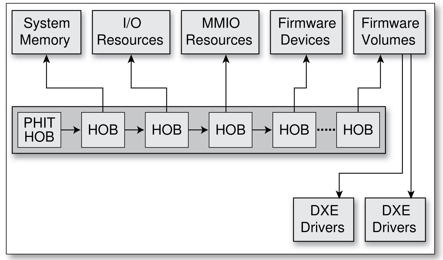
Hob list视图(图源Beyond BIOS)
//
 // Lookup DXE IPL PPI
 //
 Status = PeiServicesLocatePpi (
            &gEfiDxeIplPpiGuid,
            0,
            NULL,
            (VOID **)&TempPtr.DxeIpl
            );
 ASSERT_EFI_ERROR (Status);

 if (EFI_ERROR (Status)) {
   //
   // Report status code to indicate DXE IPL PPI could not be found.
   //
   REPORT_STATUS_CODE (
     EFI_ERROR_CODE | EFI_ERROR_MAJOR,
     (EFI_SOFTWARE_PEI_CORE | EFI_SW_PEI_CORE_EC_DXEIPL_NOT_FOUND)
     );
   CpuDeadLoop ();
 }

 //
 // Enter DxeIpl to load Dxe core.
 //
 DEBUG ((EFI_D_INFO, "DXE IPL Entry\n"));
 Status = TempPtr.DxeIpl->Entry (
                            TempPtr.DxeIpl,
                            &PrivateData.Ps,
                            PrivateData.HobList
                            );
DXE 阶段
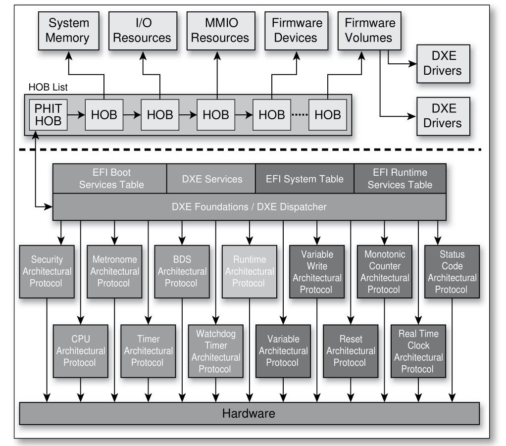
DXE阶段的入口是DxeMain,位于MdeModulePkg\Core\Dxe\DxeMain\DxeMain.c中。
首先根据HOB List初始化各种Sevices:

接着像PEI阶段调度PEIM一样,通过CoreDispatcher初始化平台相关的驱动,如PS2设备驱动,SATA设备驱动,USB设备驱动,PCIE设备驱动等(注意此时的Driver只是注册到系统中,并未执行),初始化完之后UEFI的基本环境已经准备完成了,然后调用BDS入口进入下一阶段。
BDS 阶段
BDS的入口是BdsEntry,位于MdeModulePkg\Universal\BdsDxe\BdsEntry.c中,这个阶段的主要任务是:
1.调用BdsLibConnectAll()执行(Connect)平台所需的Driver
2.找到可引导设备并调用gBS->LoadImage加载设备中的efi boot loader文件,此文件存放的路径是固定的,位于磁盘中efi/boot/目录,boot loader的命名一般为bootXX.efi,XX表示平台类别,如x86 64位则为bootx64.efi,MIPS平台则为bootmips.efi。加载成功则进入下一阶段。
TSL 阶段
此阶段是bootloader运行的阶段,它将调用ExitBootService释放EFI的资源,如DXE driver,但会保留一些必要的Run Time Service用来与OS交互,然后再启动OS。
RT 阶段
即OS运行阶段
AL 阶段
在OS运行期间发生灾难性错误,系统固件要进行错误处理和恢复时的阶段称为AL。
参考文档
Ref1:[VOLUME 1: Platform Initialization Specification] -> 5.1.2.4章节
Ref2:[VOLUME 1: Platform Initialization Specification] -> 5.1.2.1章节
Ref3:[VOLUME 1: Platform Initialization Specification] -> 5.1.1章节
版权声明:
作者:bin
链接:https://ay123.net/mystudy/uefi/955/
来源:爱影博客
文章版权归作者所有,未经允许请勿转载。

共有 0 条评论